Acoustic bearing from a 14-sample correlation, on STM32F4 and ESP32-S3, and why the two channels must be sampled in the same instant
Two microphones 10 cm apart hear a clap. The sound reaches the nearer one first (by at most 292 µs, three hundredths of the blink of an eye), and that tiny lead is a bearing: \(\sin\theta = c\tau/d\). The main page supplies everything needed to turn that into an instrument: the cross-correlation peak as the ML delay estimator, the parabolic interpolation that reads it off the sample grid, and the pairwise CRLB that says, before anything is built, how many degrees a frame of audio buys. This is the scorpion’s problem reduced to its two-legged minimum, on both default platforms.
The build also meets the one implementation detail that outranks all the estimation theory: channel simultaneity. A time-delay estimator’s entire signal is a sub-sample timing difference, so any fixed skew between the two channels’ sampling instants is not noise but a bias, indistinguishable from a rotated source, immune to averaging. The sizing section quantifies it (a multiplexed ADC’s half-sample skew costs 2° of bearing at broadside, ten times the estimator’s noise floor), and each platform section then earns its simultaneity honestly: dual-simultaneous ADC mode on the STM32F4, a shared I2S clock on the ESP32-S3.
The design, in numbers
Geometry: \(d = 100\) mm microphone spacing, \(c = 343\) m/s, so \(|\tau| \le d/c = 291.5\) µs.
Sample rate\(f_s = 48\) kHz: the physical delay range spans \(\pm 14.0\) samples, so the correlation search needs only lags \(-16..+16\).
Frame\(N = 1024\) samples (21.3 ms): about 47 bearings per second.
Source model for sizing: flat speech band, 300-3400 Hz, at 10 dB per-sample SNR on each microphone.
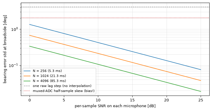
Figure 1: Bearing precision at broadside versus per-sample SNR, from the pairwise delay CRLB (both channels equally noisy, so the single-channel bound is doubled, the factor of two the main page warns about) mapped through sinθ = cτ/d, for three frame lengths. Reference lines: one raw lag step of the 48 kHz grid is 4.1° of bearing at broadside (without subsample interpolation the grid dominates everything), and a multiplexed ADC’s half-sample channel skew is a 2.0° bias that no SNR or frame length ever reduces. At the design point (N = 1024, 10 dB SNR) the estimator’s noise floor is 0.21° (asserted): about twenty times finer than the raw grid (asserted), ten times finer than the skew bias. One honest label on the whole figure: this is the anechoic, flat-band, white-noise floor; what a real room and a real voice do to it is measured further down.
rms bandwidth of the 300-3400 Hz band: 2055 Hz
physical delay range: +-291.5 us = +-14.0 samples at 48 kHz
design point: sigma_tau = 1.08 us -> 0.21 deg at broadside
Three lessons drop out of one figure. The grid is hopeless on its own: 4.1° per lag step means the raw argmax quantises the whole front hemisphere into ~28 bearings, and the three-point parabola of the main page is what turns a 48 kHz correlator into a fraction-of-a-degree instrument. The CRLB is generous: at conversational SNR a fiftieth of a second of audio bounds the bearing at a fifth of a degree, so the mathematics will not be the limit; the room-acoustics section below shows that the acoustics will be. And the skew line does not move: it is the only line on the plot that more SNR, longer frames, or better interpolation cannot touch, which is why the platform sections below spend their effort on the sampling instant rather than on the arithmetic.
Three honest physics notes before the code. The bias budget also contains the speed of sound itself: \(c\) drifts about 0.6 m/s per °C, and since \(\sin\theta \propto c\), a 10 °C error tilts an off-axis bearing by \(\tan\theta \cdot 1.8\%\): 0.7° at 35°, comparable to the skew after calibration; a temperature reading is cheap insurance. The far-field assumption (\(\sin\theta = c\tau/d\) treats the wavefront as planar) is fine beyond about a metre at this spacing but bends close in. And a single microphone pair cannot tell front from back: a source at \(\theta\) behind the array produces exactly the same delay as one at \(\theta\) in front, so every bearing this instrument reports means “in the front hemisphere, by assumption”; resolving the mirror takes a third microphone off the pair’s axis, which is where this design hands over to the array methods it is the two-element case of.
The portable core
One function, platform-independent, working on two float frames: remove each frame’s mean (electret bias and converter offsets would otherwise drag the correlation toward lag zero), correlate over the physical lags only, gate on the peak’s plausibility, interpolate, convert. Restricting the search to \(\pm 16\) lags is not an optimisation but part of the estimator: no true bearing can produce a peak at lag 40, so no such peak is allowed to win.
#include <math.h>#include <stdint.h>#define N_FRAME 1024#define MAX_LAG 16/* covers the physical +-14.0 samples */#define D_MIC 0.100f/* microphone spacing, m */#define C_SOUND 343.0f/* nominal; drifts 0.6 m/s per degC */#define FS_HZ 48000.0f/* Return codes for doa_estimate. */#define DOA_OK 0#define DOA_NO_SIGNAL -1/* frame energy below the gate */#define DOA_EDGE_PEAK -2/* peak at the search edge: not a *//* physical bearing, likely noise or *//* an out-of-range interferer */#define DOA_LOW_COHERENCE -3/* loud but not the same sound at both *//* mics (wind, handling, HVAC): the *//* most common field input, and one an *//* energy gate cannot reject */#define RHO_MIN 0.4f/* normalised-peak floor: coherent *//* frames measure 0.78-0.90 even in a *//* reverberant room, loud incoherent *//* input tops out near 0.28 (both *//* measured below) *//* Application hooks, supplied by you: the energy threshold for the gate (calibrate against your room; see the detection-theory bench protocol) and the consumer of the bearings. */float doa_gate(void);void bearing_report(float theta_deg,float tau_s);/* Delay convention, matching the main page: tau > 0 when the RIGHT channel lags the LEFT, i.e. the source is on the left side. theta is measured from broadside, positive toward the left mic. */int doa_estimate(constfloat*left,constfloat*right,float energy_gate,float*theta_deg,float*tau_s){float mean_l =0.0f, mean_r =0.0f;for(int n =0; n < N_FRAME; n++){ mean_l += left[n]; mean_r += right[n];} mean_l /= N_FRAME; mean_r /= N_FRAME;/* Energy gate: estimate only when there is something to estimate. A bearing computed on silence is uniform noise dressed as data; see the detection-theory topic for calibrating such gates. Both energies are accumulated here because the coherence gate below needs them anyway. */float energy_l =0.0f, energy_r =0.0f;for(int n =0; n < N_FRAME; n++){float vl = left[n]- mean_l;float vr = right[n]- mean_r; energy_l += vl * vl; energy_r += vr * vr;}if(energy_l < energy_gate)return DOA_NO_SIGNAL;/* r[m] = sum_n left[n] * right[n + m], m = -MAX_LAG .. +MAX_LAG. */float r[2* MAX_LAG +1];for(int m =-MAX_LAG; m <= MAX_LAG; m++){float acc =0.0f;int lo = m <0?-m :0;int hi = m >0? N_FRAME - m : N_FRAME;for(int n = lo; n < hi; n++) acc +=(left[n]- mean_l)*(right[n + m]- mean_r); r[m + MAX_LAG]= acc;}int ipk =0;for(int k =1; k <2* MAX_LAG +1; k++)if(r[k]> r[ipk]) ipk = k;if(ipk ==0|| ipk ==2* MAX_LAG)return DOA_EDGE_PEAK;/* Coherence gate: the peak, normalised by both energies, is the fraction of what the two mics heard that is the SAME sound. Loud-but-incoherent input sails through the energy gate and fails here. */float rho = r[ipk]/ sqrtf(energy_l * energy_r);if(rho < RHO_MIN)return DOA_LOW_COHERENCE;/* Three-point parabola, exactly as on the main page. */float denom = r[ipk -1]-2.0f* r[ipk]+ r[ipk +1];float delta =(denom <0.0f)?0.5f*(r[ipk -1]- r[ipk +1])/ denom :0.0f;float tau =((float)(ipk - MAX_LAG)+ delta)/ FS_HZ;float s = C_SOUND * tau / D_MIC;if(s >1.0f) s =1.0f;/* tau beyond d/c: noise pushed */if(s <-1.0f) s =-1.0f;/* the peak past endfire; clamp */*tau_s = tau;*theta_deg = asinf(s)*57.29578f;return DOA_OK;}
Per frame: \(33 \times 1024\) multiply-accumulates and one arcsine, some 47 times a second: a fraction of a percent of either target’s FPU, so there is no cycle budget to discuss; the whole engineering difficulty of this instrument lives in how left[] and right[] were filled.
The two gates answer different questions, and the second is the one field experience insists on. The energy gate asks “is anything there?”; the coherence gate asks “is it the same thing at both microphones?” The most common real-world input to a direction finder is loud and incoherent (wind on the ports, handling noise, an HVAC rumble arriving diffusely), and an energy-only gate happily converts it into confident-looking bearings scattered across the hemisphere. The normalised peak \(\rho\) is nearly free (both energies are already summed) and separates the cases by a factor of three: coherent frames measure \(\rho\) from 0.78 to 0.90 even in a reverberant room, while loud independent noise tops out near 0.28 (measured in the room-acoustics block below). A peak-prominence test (the winner must beat the best lag outside its neighbourhood by a margin) is the standard next refinement when multiple sources are in play.
Show the code
# The C path, simulated exactly: same mean removal, +-16-lag float# correlation, same parabola, same asin; run 300 times on a source at# theta = +35 deg with 10 dB per-sample SNR on each channel. The# measured bearing scatter must sit near the CRLB prediction mapped to# 35 deg (the broadside sigma grows by 1/cos(theta) off axis), and the# mean must show no material bias when the channels are simultaneous.rng = np.random.default_rng(60)N, max_lag =1024, 16theta_true = np.deg2rad(35.0)tau_true = d_mic * np.sin(theta_true) / c_snd # 167.2 ussnr =10.0# per-sample, lineardef band_noise(n_long): w = np.fft.rfftfreq(n_long, 1/ fs) spec = (np.random.default_rng(rng.integers(1<<31)).standard_normal(len(w))+1j* np.random.default_rng(rng.integers(1<<31)).standard_normal(len(w))) spec[(w < f1) | (w > f2)] =0 s = np.fft.irfft(spec, n_long)return s / np.std(s)RHO_MIN =0.4def c_equivalent(left, right): left = left - left.mean(); right = right - right.mean() lags, r = cross_correlation(left, right, max_lag=max_lag) i =int(np.argmax(r))if i in (0, len(r) -1):returnNone, None# DOA_EDGE_PEAK rho = r[i] / np.sqrt(np.sum(left**2) * np.sum(right**2))if rho < RHO_MIN:returnNone, rho # DOA_LOW_COHERENCE delta = parabolic_interpolation(r, i) tau = (lags[i] + delta) / fsreturn np.degrees(np.arcsin(np.clip(c_snd * tau / d_mic, -1, 1))), rhothetas, rhos = [], []for _ inrange(300): src = band_noise(N +256) l_ch = src[:N] + rng.standard_normal(N) / np.sqrt(snr) r_ch = (fractional_delay(src, tau_true * fs)[:N]+ rng.standard_normal(N) / np.sqrt(snr)) got, rho = c_equivalent(l_ch, r_ch)assert got isnotNone# every coherent frame passes thetas.append(got); rhos.append(rho)thetas = np.array(thetas)assertmin(rhos) >0.5, "coherent frames sit far above the 0.4 gate"sig_tau_pred = np.sqrt(2.0/ (beta2 * N * snr))sig_deg_pred = np.degrees(c_snd * sig_tau_pred / d_mic) / np.cos(theta_true)print(f"bearing: mean {thetas.mean():.2f} deg (true 35.00), "f"std {thetas.std():.3f} deg (CRLB prediction {sig_deg_pred:.3f})")assertabs(thetas.mean() -35.0) <0.15assert0.7< thetas.std() / sig_deg_pred <1.6
The sizing figure is a floor, and it is honest to say plainly what stands between it and a bench in a normal room: reverberation and the real speech spectrum. Every reflection is a delayed coherent copy of the source arriving from the wrong direction, exactly the multipath that the main page’s GCC-PHAT section treats, and the portable core above deliberately uses plain correlation, not PHAT, because at these frame rates and SNRs plain correlation is the right starting point; PHAT is the documented upgrade path once reverberation, not noise, dominates. The standard one-number summary of a room position is the direct-to-reverberant ratio (DRR): roughly 10 dB with a source about a metre away in a domestic room, falling toward 5 dB by two or three metres.
Show the code
# The same C-equivalent chain, with a diffuse reverberant tail: 16# delayed copies of the source (1-30 ms later, random inter-mic delays# across +-14 samples, i.e. arriving from everywhere), scaled to a# target DRR, plus the same 10 dB sensor noise. And the flat-band# assumption re-examined: the rms bandwidth of a tilted speech-like# spectrum, computed with the same integral as the sizing figure.def run_room(drr_db, trials=150): est, rh, gated = [], [], 0for _ inrange(trials): src = band_noise(N +2048) l_room = src.copy() r_room = fractional_delay(src, tau_true * fs)if drr_db isnotNone: g =10** (-drr_db /20) / np.sqrt(16)for _k inrange(16): d0 = rng.uniform(48, 1440) # 1-30 ms later dd = rng.uniform(-14, 14) # from anywhere l_room += g * fractional_delay(src, d0) r_room += g * fractional_delay(src, d0 + dd) th, rho = c_equivalent(l_room[:N] + rng.standard_normal(N) / np.sqrt(snr), r_room[:N] + rng.standard_normal(N) / np.sqrt(snr))if th isNone: gated +=1else: est.append(th); rh.append(rho)return np.array(est), np.array(rh), gatedstds, frac_off, gated_total = {}, {}, 0for drr in (None, 10, 6): e, rh, gated = run_room(drr) stds[drr], frac_off[drr] = e.std(), np.mean(np.abs(e -35) >1) gated_total += gatedprint(f"DRR {'inf'if drr isNoneelse drr:>3} dB: bearing std "f"{e.std():.2f} deg, {frac_off[drr]:.0%} of frames "f"beyond 1 deg, median rho {np.median(rh):.2f}, gated {gated}")assert gated_total ==0, "every coherent frame passes, reverberant or not"# Loud-but-incoherent input: independent band noise at both mics.rho_inc, rejected = [], 0for _ inrange(150): a = band_noise(N +64)[:N] *3.0+ rng.standard_normal(N) *0.3 b = band_noise(N +64)[:N] *3.0+ rng.standard_normal(N) *0.3 th, rho = c_equivalent(a, b)if th isNone: rejected +=1if rho isnotNone: rho_inc.append(rho)print(f"loud incoherent frames: {rejected}/150 rejected by the gates, "f"max rho {np.max(rho_inc):.2f} (gate at {RHO_MIN})")# The flat 300-3400 Hz band vs a speech-like tilt (flat to 500 Hz,# then falling), through the same rms-bandwidth integral.f_grid = np.linspace(f1, f2, 2000)for slope_db_oct in (6.0, 9.0): S_tilt = np.where(f_grid <500, 1.0, (f_grid /500.0) ** (-slope_db_oct / (10* np.log10(2)))) f_rms = np.sqrt(np.sum(f_grid**2* S_tilt) / np.sum(S_tilt))print(f"speech tilt -{slope_db_oct:.0f} dB/oct: rms bandwidth "f"{f_rms:.0f} Hz (flat band: 2055 Hz)")assert700< f_rms <1200# The prose's ratio claims, asserted as relationships (arc rule #4):assert1.8< stds[10] / stds[None] <3.5# "two to three times" at DRR 10assert3.0< stds[6] / stds[None] <6.0# "around four times" at DRR 6assert0.10< frac_off[10] <0.30# "a fifth of frames..."assert0.30< frac_off[6] <0.55# "...to nearly half"assert rejected ==150# incoherence never yields a bearingassert np.max(rho_inc) < RHO_MIN
DRR inf dB: bearing std 0.33 deg, 0% of frames beyond 1 deg, median rho 0.90, gated 0
DRR  10 dB: bearing std 0.75 deg, 20% of frames beyond 1 deg, median rho 0.85, gated 0
DRR   6 dB: bearing std 1.35 deg, 44% of frames beyond 1 deg, median rho 0.77, gated 0
loud incoherent frames: 150/150 rejected by the gates, max rho 0.28 (gate at 0.4)
speech tilt -6 dB/oct: rms bandwidth 1102 Hz (flat band: 2055 Hz)
speech tilt -9 dB/oct: rms bandwidth 784 Hz (flat band: 2055 Hz)
Three field conclusions, all measured above. First, acoustics sets the accuracy: at DRR 10 dB the bearing scatter is two to three times the anechoic scatter, at 6 dB around four times, with a fifth to nearly half of the frames landing more than a degree off; no line of the sizing figure moves, the room simply is not in that figure. Second, the spectrum matters as much as the SNR: a real voice’s high-frequency roll-off cuts the rms bandwidth from the flat-band 2055 Hz to roughly 800 to 1100 Hz, another factor of two on the delay error before any acoustics, which is why the calibration below uses a noise source (which genuinely fills the band) rather than speech. Third, the coherence gate earns its place: loud incoherent input never produces a bearing, while every coherent frame, reverberant or not, passes.
What a half-sample of skew does
The obvious two-channel design (one ADC, two multiplexed channels, alternating conversions) samples the right microphone half a period after the left one, always. That constant \(T_s/2 = 10.4\) µs enters the estimate as a delay that no real source produced:
Show the code
# The bias is deterministic: added skew shifts sin(theta) by# c * skew / d, and the off-axis growth is the 1/cos(theta) of the# arcsine mapping. No averaging touches it.for theta_deg in (0.0, 30.0, 60.0): s_true = np.sin(np.deg2rad(theta_deg)) s_skew = np.clip(s_true + c_snd * skew / d_mic, -1, 1) bias = np.degrees(np.arcsin(s_skew)) - theta_degprint(f"true bearing {theta_deg:4.0f} deg -> read "f"{np.degrees(np.arcsin(s_skew)):6.2f} deg (bias {bias:+.2f})")if theta_deg ==0.0:assertabs(bias -2.05) <0.05if theta_deg ==60.0:assertabs(bias -4.39) <0.05
Two degrees at broadside, four and a half at 60°, forever. A fixed skew can be calibrated out (below), but only if it is actually fixed, and a multiplexer shared with other duties, a variable ADC sequence, or independent free-running clocks on the two channels all break that promise. The clean solutions cost nothing on these platforms: sample both channels on the same trigger edge.
On the STM32F4 (NUCLEO-F446RE)
The F446 has three ADCs, and its dual regular simultaneous mode exists for exactly this problem: ADC1 and ADC2 convert their channels on the same trigger edge, and the combined result arrives as one 32-bit word (ADC2 in the high half) through the common data register: one DMA stream, zero skew. The trigger chain is the proven TIM-TRGO pattern of the CFAR and lock-in pages, at 48 kHz.
#include "stm32f4xx_hal.h"staticuint32_t adc_buf[2* N_FRAME];/* packed ADC2<<16 | ADC1 */staticfloat frame_l[N_FRAME], frame_r[N_FRAME];/* TIM2 update -> TRGO at 48 kHz; ADC1 (PA0, left) and ADC2 (PA1, right) convert simultaneously on each edge; DMA moves the packed pair. Buffer = 2 frames, so each half/full callback is one frame. */void doa_start(TIM_HandleTypeDef *tim2, ADC_HandleTypeDef *adc1, ADC_HandleTypeDef *adc2,uint32_t timer_bus_hz){ tim2->Init.Prescaler =0; tim2->Init.Period = timer_bus_hz /48000u-1u; HAL_TIM_Base_Init(tim2); TIM_MasterConfigTypeDef ms ={0}; ms.MasterOutputTrigger = TIM_TRGO_UPDATE; HAL_TIMEx_MasterConfigSynchronization(tim2,&ms);/* Master: ADC1, hardware-triggered. */ adc1->Init.Resolution = ADC_RESOLUTION_12B; adc1->Init.ExternalTrigConv = ADC_EXTERNALTRIGCONV_T2_TRGO; adc1->Init.ExternalTrigConvEdge = ADC_EXTERNALTRIGCONVEDGE_RISING; adc1->Init.ContinuousConvMode = DISABLE; adc1->Init.DMAContinuousRequests = ENABLE; HAL_ADC_Init(adc1);/* Slave: ADC2 follows the master's trigger in dual mode. */ adc2->Init.Resolution = ADC_RESOLUTION_12B; adc2->Init.ExternalTrigConv = ADC_SOFTWARE_START; adc2->Init.ContinuousConvMode = DISABLE; HAL_ADC_Init(adc2); ADC_ChannelConfTypeDef ch ={0}; ch.Rank =1; ch.SamplingTime = ADC_SAMPLETIME_56CYCLES; ch.Channel = ADC_CHANNEL_0;/* PA0: left mic */ HAL_ADC_ConfigChannel(adc1,&ch); ch.Channel = ADC_CHANNEL_1;/* PA1: right mic */ HAL_ADC_ConfigChannel(adc2,&ch); ADC_MultiModeTypeDef mm ={0}; mm.Mode = ADC_DUALMODE_REGSIMULT; mm.DMAAccessMode = ADC_DMAACCESSMODE_2;/* one 32-bit word/pair */ mm.TwoSamplingDelay = ADC_TWOSAMPLINGDELAY_5CYCLES; HAL_ADCEx_MultiModeConfigChannel(adc1,&mm); HAL_ADCEx_MultiModeStart_DMA(adc1, adc_buf,2* N_FRAME); HAL_TIM_Base_Start(tim2);}/* Deinterleave one frame and run the estimator. */staticvoid process(constuint32_t*packed){float theta, tau;for(int n =0; n < N_FRAME; n++){ frame_l[n]=(float)(packed[n]&0xFFFFu); frame_r[n]=(float)(packed[n]>>16);}if(doa_estimate(frame_l, frame_r, doa_gate(),&theta,&tau)== DOA_OK) bearing_report(theta, tau);/* your hooks */}void HAL_ADC_ConvHalfCpltCallback(ADC_HandleTypeDef *h){ process(adc_buf);}void HAL_ADC_ConvCpltCallback(ADC_HandleTypeDef *h){ process(adc_buf + N_FRAME);}
(doa_gate() and bearing_report() are the application hooks declared with the portable core: the first returns the energy threshold (calibrate it against your room per the detection-theory bench protocol), the second consumes the bearings.) The analogue front end is two electret capsules with matched preamps, AC-coupled and biased to mid-rail. Matched matters less than it sounds: a per-channel gain error scales the correlation without moving its peak, so gain mismatch, the usual analogue headache, is harmless here. What is not harmless is a mismatch in the two preamps’ filter corners, because a first-order high-pass at \(f_c\) contributes a group delay of \(\tau_{gr}(f) = \frac{1}{2\pi f_c}\cdot\frac{1}{1 + (f/f_c)^2}\): two “identical” 100 Hz corners that actually sit at 90 and 110 Hz disagree by about 25 µs of group delay at the 300 Hz band edge (and by more further down), twenty-five times this design’s 1.1 µs noise floor. Keep the corners a decade below the 300 Hz band edge and this term shrinks to nothing; or let the broadside calibration below absorb what remains.
On the ESP32-S3
Digital MEMS microphones make the simultaneity story even cleaner: two I2S microphones (INMP441-class) share one bus (same BCLK, same WS) with one mic strapped to the left slot and the other to the right. The sampling instants of both are slaved to the same word-select edge the ESP32-S3 generates, so channel skew is fixed by construction and absorbed into the one-time calibration.
One I2S subtlety belongs in the open rather than in a footnote: the two mics answer on opposite WS half-frames, and whether their internal decimators sample at identical instants or half a frame apart is a datasheet property of the microphone, not of the ESP32. That is a fixed offset on a shared clock (exactly the kind the next section removes), but it is a reason the broadside calibration is mandatory rather than optional on this platform.
Calibration and validation, by physics
Calibrate at broadside. Put a source (a phone playing noise is fine) equidistant from both microphones: the geometry everyone can set up exactly, since equidistant just means “on the perpendicular bisector, a metre or two out”. The true delay is zero by symmetry, so whatever mean delay the instrument reports is its total residual skew (converter timing, preamp group-delay mismatch, mic decimator offsets, everything) as one number. Store \(\tau_{\text{cal}}\) and subtract it from every estimate. This single measurement converts every fixed timing asymmetry in the chain into a solved problem, which is why the platform sections above only had to guarantee that the skew is fixed, not that it is zero.
Then validate the noise floor against the theory, in a setting the theory describes. The sizing figure’s promise is an anechoic one, so run the CRLB check where the direct path actually dominates: a band-filling noise source 20 to 30 cm from the pair (or outdoors, away from surfaces). There the calibrated bearings should scatter around zero with the standard deviation the sizing figure promised at your measured SNR: a direct, hardware-in-the-loop check of the pairwise CRLB, in the same spirit as counting a CFAR detector’s false alarms. At a metre or two in a normal room, expect three to five times that floor instead; that inflation is the room-acoustics section’s measurement, not a fault. A gap beyond it points at the fixed-skew suspects (calibration drift, mismatched preamp corners), which is exactly what makes the two regimes worth separating on the bench. Then walk the source in 10° steps: the mean bearing should track, the scatter should grow as \(1/\cos\theta\) toward endfire (the arcsine mapping stretches near its edges), and beyond about ±70° the estimates should start clamping: all three behaviours are predictions, and a bench session that reproduces them has verified this page’s theory with a phone and a protractor.
References
Source Code
---title: "A Two-Microphone Direction Finder"subtitle: "Acoustic bearing from a 14-sample correlation, on STM32F4 and ESP32-S3, and why the two channels must be sampled in the same instant"description-meta: "Acoustic bearing from a 14-sample correlation on the STM32F4 and ESP32-S3, and why both channels must be sampled in the same instant."bibliography: ../../references.bib---Two microphones 10 cm apart hear a clap. The sound reaches the nearer one first (by at most 292 µs, three hundredths of the blink of an eye), and that tiny lead is a bearing: $\sin\theta = c\tau/d$. [The main page](index.qmd) supplies everything needed to turn that into an instrument: the cross-correlation peak as the ML delay estimator, the parabolic interpolation that reads it off the sample grid, and the pairwise CRLB that says, *before anything is built*, how many degrees a frame of audio buys. This is the [scorpion's problem](../beamforming/index.qmd#the-scorpion-simulation) reduced to its two-legged minimum, on both default platforms.The build also meets the one implementation detail that outranks all the estimation theory: **channel simultaneity**. A time-delay estimator's entire signal is a sub-sample timing difference, so any fixed skew between the two channels' sampling instants is not noise but a *bias*, indistinguishable from a rotated source, immune to averaging. The sizing section quantifies it (a multiplexed ADC's half-sample skew costs 2° of bearing at broadside, ten times the estimator's noise floor), and each platform section then earns its simultaneity honestly: dual-simultaneous ADC mode on the STM32F4, a shared I2S clock on the ESP32-S3.```{python}#| echo: falseimport numpy as npimport matplotlib.pyplot as pltfrom tde import (cross_correlation, crlb_delay_pair, estimate_delay, fractional_delay, parabolic_interpolation, rms_bandwidth)```<hr>## The design, in numbers- **Geometry**: $d = 100$ mm microphone spacing, $c = 343$ m/s, so $|\tau| \le d/c = 291.5$ µs.- **Sample rate** $f_s = 48$ kHz: the physical delay range spans $\pm 14.0$ samples, so the correlation search needs only lags $-16..+16$.- **Frame** $N = 1024$ samples (21.3 ms): about 47 bearings per second.- **Source model for sizing**: flat speech band, 300-3400 Hz, at 10 dB per-sample SNR on each microphone.```{python}#| label: fig-sizing#| fig-cap: "Bearing precision at broadside versus per-sample SNR, from the pairwise delay CRLB (both channels equally noisy, so the single-channel bound is doubled, the factor of two the main page warns about) mapped through sinθ = cτ/d, for three frame lengths. Reference lines: one raw lag step of the 48 kHz grid is 4.1° of bearing at broadside (without subsample interpolation the grid dominates everything), and a multiplexed ADC's half-sample channel skew is a 2.0° bias that no SNR or frame length ever reduces. At the design point (N = 1024, 10 dB SNR) the estimator's noise floor is 0.21° (asserted): about twenty times finer than the raw grid (asserted), ten times finer than the skew bias. One honest label on the whole figure: this is the anechoic, flat-band, white-noise floor; what a real room and a real voice do to it is measured further down."d_mic, c_snd, fs =0.100, 343.0, 48000.0f1, f2 =300.0, 3400.0beta2 = (2* np.pi) **2* (f2**3- f1**3) / (3* (f2 - f1))beta = np.sqrt(beta2) # rms bandwidth, rad/stau_max = d_mic / c_sndlag_step_deg = np.degrees(np.arcsin(c_snd / (fs * d_mic)))skew =0.5/ fs # muxed-ADC half-sample skewskew_deg = np.degrees(np.arcsin(c_snd * skew / d_mic))snr_db = np.linspace(0, 25, 120)fig, ax = plt.subplots(figsize=(7.5, 4))for N in (256, 1024, 4096): enr = N *10** (snr_db /10) sig_tau = np.sqrt(2.0/ (beta2 * enr)) # pairwise: 2x single sig_deg = np.degrees(c_snd * sig_tau / d_mic) # at broadside ax.semilogy(snr_db, sig_deg, lw=1.3, label=f'N = {N} ({N/fs*1e3:.1f} ms)')ax.axhline(lag_step_deg, color='gray', ls='--', lw=1, label='one raw lag step (no interpolation)')ax.axhline(skew_deg, color='C3', ls=':', lw=1.2, label='muxed-ADC half-sample skew (bias!)')ax.set_xlabel('per-sample SNR on each microphone [dB]')ax.set_ylabel('bearing error std at broadside [deg]')ax.legend(fontsize=8); ax.grid(True, alpha=0.3, which='both')fig.tight_layout(); plt.show()enr_design =1024*10.0sig_tau_design = np.sqrt(2.0/ (beta2 * enr_design))sig_deg_design = np.degrees(c_snd * sig_tau_design / d_mic)print(f"rms bandwidth of the 300-3400 Hz band: {beta/2/np.pi:.0f} Hz")print(f"physical delay range: +-{tau_max*1e6:.1f} us = "f"+-{tau_max*fs:.1f} samples at 48 kHz")print(f"design point: sigma_tau = {sig_tau_design*1e6:.2f} us -> "f"{sig_deg_design:.2f} deg at broadside")assertabs(tau_max * fs -14.0) <0.05assertabs(lag_step_deg -4.1) <0.05assertabs(skew_deg -2.05) <0.05assertabs(sig_deg_design -0.21) <0.01assert15< lag_step_deg / sig_deg_design <25# "twenty times finer"assertabs(beta /2/ np.pi -2055) <5```Three lessons drop out of one figure. The **grid is hopeless on its own**: 4.1° per lag step means the raw argmax quantises the whole front hemisphere into ~28 bearings, and the three-point parabola of the main page is what turns a 48 kHz correlator into a fraction-of-a-degree instrument. The **CRLB is generous**: at conversational SNR a fiftieth of a second of audio bounds the bearing at a fifth of a degree, so the mathematics will not be the limit; the room-acoustics section below shows that the *acoustics* will be. And the **skew line does not move**: it is the only line on the plot that more SNR, longer frames, or better interpolation cannot touch, which is why the platform sections below spend their effort on the sampling instant rather than on the arithmetic.Three honest physics notes before the code. The bias budget also contains the speed of sound itself: $c$ drifts about 0.6 m/s per °C, and since $\sin\theta \propto c$, a 10 °C error tilts an off-axis bearing by $\tan\theta \cdot 1.8\%$: 0.7° at 35°, comparable to the skew after calibration; a temperature reading is cheap insurance. The far-field assumption ($\sin\theta = c\tau/d$ treats the wavefront as planar) is fine beyond about a metre at this spacing but bends close in. And a single microphone pair cannot tell front from back: a source at $\theta$ behind the array produces exactly the same delay as one at $\theta$ in front, so every bearing this instrument reports means "in the front hemisphere, by assumption"; resolving the mirror takes a third microphone off the pair's axis, which is where this design hands over to the [array methods](../beamforming/index.qmd) it is the two-element case of.<hr>## The portable coreOne function, platform-independent, working on two float frames: remove each frame's mean (electret bias and converter offsets would otherwise drag the correlation toward lag zero), correlate over the physical lags only, gate on the peak's plausibility, interpolate, convert. Restricting the search to $\pm 16$ lags is not an optimisation but part of the estimator: no true bearing can produce a peak at lag 40, so no such peak is allowed to win.```c#include <math.h>#include <stdint.h>#define N_FRAME 1024#define MAX_LAG 16/* covers the physical +-14.0 samples */#define D_MIC 0.100f/* microphone spacing, m */#define C_SOUND 343.0f/* nominal; drifts 0.6 m/s per degC */#define FS_HZ 48000.0f/* Return codes for doa_estimate. */#define DOA_OK 0#define DOA_NO_SIGNAL -1/* frame energy below the gate */#define DOA_EDGE_PEAK -2/* peak at the search edge: not a *//* physical bearing, likely noise or *//* an out-of-range interferer */#define DOA_LOW_COHERENCE -3/* loud but not the same sound at both *//* mics (wind, handling, HVAC): the *//* most common field input, and one an *//* energy gate cannot reject */#define RHO_MIN 0.4f/* normalised-peak floor: coherent *//* frames measure 0.78-0.90 even in a *//* reverberant room, loud incoherent *//* input tops out near 0.28 (both *//* measured below) *//* Application hooks, supplied by you: the energy threshold for the gate (calibrate against your room; see the detection-theory bench protocol) and the consumer of the bearings. */float doa_gate(void);void bearing_report(float theta_deg,float tau_s);/* Delay convention, matching the main page: tau > 0 when the RIGHT channel lags the LEFT, i.e. the source is on the left side. theta is measured from broadside, positive toward the left mic. */int doa_estimate(constfloat*left,constfloat*right,float energy_gate,float*theta_deg,float*tau_s){float mean_l =0.0f, mean_r =0.0f;for(int n =0; n < N_FRAME; n++){ mean_l += left[n]; mean_r += right[n];} mean_l /= N_FRAME; mean_r /= N_FRAME;/* Energy gate: estimate only when there is something to estimate. A bearing computed on silence is uniform noise dressed as data; see the detection-theory topic for calibrating such gates. Both energies are accumulated here because the coherence gate below needs them anyway. */float energy_l =0.0f, energy_r =0.0f;for(int n =0; n < N_FRAME; n++){float vl = left[n]- mean_l;float vr = right[n]- mean_r; energy_l += vl * vl; energy_r += vr * vr;}if(energy_l < energy_gate)return DOA_NO_SIGNAL;/* r[m] = sum_n left[n] * right[n + m], m = -MAX_LAG .. +MAX_LAG. */float r[2* MAX_LAG +1];for(int m =-MAX_LAG; m <= MAX_LAG; m++){float acc =0.0f;int lo = m <0?-m :0;int hi = m >0? N_FRAME - m : N_FRAME;for(int n = lo; n < hi; n++) acc +=(left[n]- mean_l)*(right[n + m]- mean_r); r[m + MAX_LAG]= acc;}int ipk =0;for(int k =1; k <2* MAX_LAG +1; k++)if(r[k]> r[ipk]) ipk = k;if(ipk ==0|| ipk ==2* MAX_LAG)return DOA_EDGE_PEAK;/* Coherence gate: the peak, normalised by both energies, is the fraction of what the two mics heard that is the SAME sound. Loud-but-incoherent input sails through the energy gate and fails here. */float rho = r[ipk]/ sqrtf(energy_l * energy_r);if(rho < RHO_MIN)return DOA_LOW_COHERENCE;/* Three-point parabola, exactly as on the main page. */float denom = r[ipk -1]-2.0f* r[ipk]+ r[ipk +1];float delta =(denom <0.0f)?0.5f*(r[ipk -1]- r[ipk +1])/ denom :0.0f;float tau =((float)(ipk - MAX_LAG)+ delta)/ FS_HZ;float s = C_SOUND * tau / D_MIC;if(s >1.0f) s =1.0f;/* tau beyond d/c: noise pushed */if(s <-1.0f) s =-1.0f;/* the peak past endfire; clamp */*tau_s = tau;*theta_deg = asinf(s)*57.29578f;return DOA_OK;}```Per frame: $33 \times 1024$ multiply-accumulates and one arcsine, some 47 times a second: a fraction of a percent of either target's FPU, so there is no cycle budget to discuss; the whole engineering difficulty of this instrument lives in how `left[]` and `right[]` were filled.The two gates answer different questions, and the second is the one field experience insists on. The energy gate asks "is anything there?"; the coherence gate asks "is it the *same* thing at both microphones?" The most common real-world input to a direction finder is loud and incoherent (wind on the ports, handling noise, an HVAC rumble arriving diffusely), and an energy-only gate happily converts it into confident-looking bearings scattered across the hemisphere. The normalised peak $\rho$ is nearly free (both energies are already summed) and separates the cases by a factor of three: coherent frames measure $\rho$ from 0.78 to 0.90 even in a reverberant room, while loud independent noise tops out near 0.28 (measured in the room-acoustics block below). A peak-prominence test (the winner must beat the best lag outside its neighbourhood by a margin) is the standard next refinement when multiple sources are in play.```{python}#| label: c-chain-check# The C path, simulated exactly: same mean removal, +-16-lag float# correlation, same parabola, same asin; run 300 times on a source at# theta = +35 deg with 10 dB per-sample SNR on each channel. The# measured bearing scatter must sit near the CRLB prediction mapped to# 35 deg (the broadside sigma grows by 1/cos(theta) off axis), and the# mean must show no material bias when the channels are simultaneous.rng = np.random.default_rng(60)N, max_lag =1024, 16theta_true = np.deg2rad(35.0)tau_true = d_mic * np.sin(theta_true) / c_snd # 167.2 ussnr =10.0# per-sample, lineardef band_noise(n_long): w = np.fft.rfftfreq(n_long, 1/ fs) spec = (np.random.default_rng(rng.integers(1<<31)).standard_normal(len(w))+1j* np.random.default_rng(rng.integers(1<<31)).standard_normal(len(w))) spec[(w < f1) | (w > f2)] =0 s = np.fft.irfft(spec, n_long)return s / np.std(s)RHO_MIN =0.4def c_equivalent(left, right): left = left - left.mean(); right = right - right.mean() lags, r = cross_correlation(left, right, max_lag=max_lag) i =int(np.argmax(r))if i in (0, len(r) -1):returnNone, None# DOA_EDGE_PEAK rho = r[i] / np.sqrt(np.sum(left**2) * np.sum(right**2))if rho < RHO_MIN:returnNone, rho # DOA_LOW_COHERENCE delta = parabolic_interpolation(r, i) tau = (lags[i] + delta) / fsreturn np.degrees(np.arcsin(np.clip(c_snd * tau / d_mic, -1, 1))), rhothetas, rhos = [], []for _ inrange(300): src = band_noise(N +256) l_ch = src[:N] + rng.standard_normal(N) / np.sqrt(snr) r_ch = (fractional_delay(src, tau_true * fs)[:N]+ rng.standard_normal(N) / np.sqrt(snr)) got, rho = c_equivalent(l_ch, r_ch)assert got isnotNone# every coherent frame passes thetas.append(got); rhos.append(rho)thetas = np.array(thetas)assertmin(rhos) >0.5, "coherent frames sit far above the 0.4 gate"sig_tau_pred = np.sqrt(2.0/ (beta2 * N * snr))sig_deg_pred = np.degrees(c_snd * sig_tau_pred / d_mic) / np.cos(theta_true)print(f"bearing: mean {thetas.mean():.2f} deg (true 35.00), "f"std {thetas.std():.3f} deg (CRLB prediction {sig_deg_pred:.3f})")assertabs(thetas.mean() -35.0) <0.15assert0.7< thetas.std() / sig_deg_pred <1.6```<hr>## What a real room does to the budgetThe sizing figure is a floor, and it is honest to say plainly what stands between it and a bench in a normal room: **reverberation** and the **real speech spectrum**. Every reflection is a delayed coherent copy of the source arriving from the wrong direction, exactly the multipath that [the main page's GCC-PHAT section](index.qmd#when-the-room-echoes-gcc-phat) treats, and the portable core above deliberately uses plain correlation, not PHAT, because at these frame rates and SNRs plain correlation is the right *starting* point; PHAT is the documented upgrade path once reverberation, not noise, dominates. The standard one-number summary of a room position is the direct-to-reverberant ratio (DRR): roughly 10 dB with a source about a metre away in a domestic room, falling toward 5 dB by two or three metres.```{python}#| label: room-acoustics# The same C-equivalent chain, with a diffuse reverberant tail: 16# delayed copies of the source (1-30 ms later, random inter-mic delays# across +-14 samples, i.e. arriving from everywhere), scaled to a# target DRR, plus the same 10 dB sensor noise. And the flat-band# assumption re-examined: the rms bandwidth of a tilted speech-like# spectrum, computed with the same integral as the sizing figure.def run_room(drr_db, trials=150): est, rh, gated = [], [], 0for _ inrange(trials): src = band_noise(N +2048) l_room = src.copy() r_room = fractional_delay(src, tau_true * fs)if drr_db isnotNone: g =10** (-drr_db /20) / np.sqrt(16)for _k inrange(16): d0 = rng.uniform(48, 1440) # 1-30 ms later dd = rng.uniform(-14, 14) # from anywhere l_room += g * fractional_delay(src, d0) r_room += g * fractional_delay(src, d0 + dd) th, rho = c_equivalent(l_room[:N] + rng.standard_normal(N) / np.sqrt(snr), r_room[:N] + rng.standard_normal(N) / np.sqrt(snr))if th isNone: gated +=1else: est.append(th); rh.append(rho)return np.array(est), np.array(rh), gatedstds, frac_off, gated_total = {}, {}, 0for drr in (None, 10, 6): e, rh, gated = run_room(drr) stds[drr], frac_off[drr] = e.std(), np.mean(np.abs(e -35) >1) gated_total += gatedprint(f"DRR {'inf'if drr isNoneelse drr:>3} dB: bearing std "f"{e.std():.2f} deg, {frac_off[drr]:.0%} of frames "f"beyond 1 deg, median rho {np.median(rh):.2f}, gated {gated}")assert gated_total ==0, "every coherent frame passes, reverberant or not"# Loud-but-incoherent input: independent band noise at both mics.rho_inc, rejected = [], 0for _ inrange(150): a = band_noise(N +64)[:N] *3.0+ rng.standard_normal(N) *0.3 b = band_noise(N +64)[:N] *3.0+ rng.standard_normal(N) *0.3 th, rho = c_equivalent(a, b)if th isNone: rejected +=1if rho isnotNone: rho_inc.append(rho)print(f"loud incoherent frames: {rejected}/150 rejected by the gates, "f"max rho {np.max(rho_inc):.2f} (gate at {RHO_MIN})")# The flat 300-3400 Hz band vs a speech-like tilt (flat to 500 Hz,# then falling), through the same rms-bandwidth integral.f_grid = np.linspace(f1, f2, 2000)for slope_db_oct in (6.0, 9.0): S_tilt = np.where(f_grid <500, 1.0, (f_grid /500.0) ** (-slope_db_oct / (10* np.log10(2)))) f_rms = np.sqrt(np.sum(f_grid**2* S_tilt) / np.sum(S_tilt))print(f"speech tilt -{slope_db_oct:.0f} dB/oct: rms bandwidth "f"{f_rms:.0f} Hz (flat band: 2055 Hz)")assert700< f_rms <1200# The prose's ratio claims, asserted as relationships (arc rule #4):assert1.8< stds[10] / stds[None] <3.5# "two to three times" at DRR 10assert3.0< stds[6] / stds[None] <6.0# "around four times" at DRR 6assert0.10< frac_off[10] <0.30# "a fifth of frames..."assert0.30< frac_off[6] <0.55# "...to nearly half"assert rejected ==150# incoherence never yields a bearingassert np.max(rho_inc) < RHO_MIN```Three field conclusions, all measured above. First, **acoustics sets the accuracy**: at DRR 10 dB the bearing scatter is two to three times the anechoic scatter, at 6 dB around four times, with a fifth to nearly half of the frames landing more than a degree off; no line of the sizing figure moves, the room simply is not in that figure. Second, **the spectrum matters as much as the SNR**: a real voice's high-frequency roll-off cuts the rms bandwidth from the flat-band 2055 Hz to roughly 800 to 1100 Hz, another factor of two on the delay error before any acoustics, which is why the calibration below uses a *noise source* (which genuinely fills the band) rather than speech. Third, the **coherence gate earns its place**: loud incoherent input never produces a bearing, while every coherent frame, reverberant or not, passes.<hr>## What a half-sample of skew doesThe obvious two-channel design (one ADC, two multiplexed channels, alternating conversions) samples the right microphone half a period after the left one, always. That constant $T_s/2 = 10.4$ µs enters the estimate as a delay that no real source produced:```{python}#| label: skew-bias# The bias is deterministic: added skew shifts sin(theta) by# c * skew / d, and the off-axis growth is the 1/cos(theta) of the# arcsine mapping. No averaging touches it.for theta_deg in (0.0, 30.0, 60.0): s_true = np.sin(np.deg2rad(theta_deg)) s_skew = np.clip(s_true + c_snd * skew / d_mic, -1, 1) bias = np.degrees(np.arcsin(s_skew)) - theta_degprint(f"true bearing {theta_deg:4.0f} deg -> read "f"{np.degrees(np.arcsin(s_skew)):6.2f} deg (bias {bias:+.2f})")if theta_deg ==0.0:assertabs(bias -2.05) <0.05if theta_deg ==60.0:assertabs(bias -4.39) <0.05```Two degrees at broadside, four and a half at 60°, forever. A fixed skew *can* be calibrated out (below), but only if it is actually fixed, and a multiplexer shared with other duties, a variable ADC sequence, or independent free-running clocks on the two channels all break that promise. The clean solutions cost nothing on these platforms: sample both channels on the *same trigger edge*.<hr>## On the STM32F4 (NUCLEO-F446RE)The F446 has three ADCs, and its **dual regular simultaneous mode** exists for exactly this problem: ADC1 and ADC2 convert their channels on the same trigger edge, and the combined result arrives as one 32-bit word (ADC2 in the high half) through the common data register: one DMA stream, zero skew. The trigger chain is the proven TIM-TRGO pattern of the [CFAR](../detection-theory/embedded.qmd) and [lock-in](../lock-in-detection/embedded.qmd) pages, at 48 kHz.```c#include "stm32f4xx_hal.h"staticuint32_t adc_buf[2* N_FRAME];/* packed ADC2<<16 | ADC1 */staticfloat frame_l[N_FRAME], frame_r[N_FRAME];/* TIM2 update -> TRGO at 48 kHz; ADC1 (PA0, left) and ADC2 (PA1, right) convert simultaneously on each edge; DMA moves the packed pair. Buffer = 2 frames, so each half/full callback is one frame. */void doa_start(TIM_HandleTypeDef *tim2, ADC_HandleTypeDef *adc1, ADC_HandleTypeDef *adc2,uint32_t timer_bus_hz){ tim2->Init.Prescaler =0; tim2->Init.Period = timer_bus_hz /48000u-1u; HAL_TIM_Base_Init(tim2); TIM_MasterConfigTypeDef ms ={0}; ms.MasterOutputTrigger = TIM_TRGO_UPDATE; HAL_TIMEx_MasterConfigSynchronization(tim2,&ms);/* Master: ADC1, hardware-triggered. */ adc1->Init.Resolution = ADC_RESOLUTION_12B; adc1->Init.ExternalTrigConv = ADC_EXTERNALTRIGCONV_T2_TRGO; adc1->Init.ExternalTrigConvEdge = ADC_EXTERNALTRIGCONVEDGE_RISING; adc1->Init.ContinuousConvMode = DISABLE; adc1->Init.DMAContinuousRequests = ENABLE; HAL_ADC_Init(adc1);/* Slave: ADC2 follows the master's trigger in dual mode. */ adc2->Init.Resolution = ADC_RESOLUTION_12B; adc2->Init.ExternalTrigConv = ADC_SOFTWARE_START; adc2->Init.ContinuousConvMode = DISABLE; HAL_ADC_Init(adc2); ADC_ChannelConfTypeDef ch ={0}; ch.Rank =1; ch.SamplingTime = ADC_SAMPLETIME_56CYCLES; ch.Channel = ADC_CHANNEL_0;/* PA0: left mic */ HAL_ADC_ConfigChannel(adc1,&ch); ch.Channel = ADC_CHANNEL_1;/* PA1: right mic */ HAL_ADC_ConfigChannel(adc2,&ch); ADC_MultiModeTypeDef mm ={0}; mm.Mode = ADC_DUALMODE_REGSIMULT; mm.DMAAccessMode = ADC_DMAACCESSMODE_2;/* one 32-bit word/pair */ mm.TwoSamplingDelay = ADC_TWOSAMPLINGDELAY_5CYCLES; HAL_ADCEx_MultiModeConfigChannel(adc1,&mm); HAL_ADCEx_MultiModeStart_DMA(adc1, adc_buf,2* N_FRAME); HAL_TIM_Base_Start(tim2);}/* Deinterleave one frame and run the estimator. */staticvoid process(constuint32_t*packed){float theta, tau;for(int n =0; n < N_FRAME; n++){ frame_l[n]=(float)(packed[n]&0xFFFFu); frame_r[n]=(float)(packed[n]>>16);}if(doa_estimate(frame_l, frame_r, doa_gate(),&theta,&tau)== DOA_OK) bearing_report(theta, tau);/* your hooks */}void HAL_ADC_ConvHalfCpltCallback(ADC_HandleTypeDef *h){ process(adc_buf);}void HAL_ADC_ConvCpltCallback(ADC_HandleTypeDef *h){ process(adc_buf + N_FRAME);}```(`doa_gate()` and `bearing_report()` are the application hooks declared with the portable core: the first returns the energy threshold (calibrate it against your room per the [detection-theory bench protocol](../detection-theory/embedded.qmd#validation-by-counting-the-bench-protocol)), the second consumes the bearings.) The analogue front end is two electret capsules with matched preamps, AC-coupled and biased to mid-rail. *Matched* matters less than it sounds: a per-channel gain error scales the correlation without moving its peak, so gain mismatch, the usual analogue headache, is harmless here. What is **not** harmless is a mismatch in the two preamps' filter corners, because a first-order high-pass at $f_c$ contributes a group delay of $\tau_{gr}(f) = \frac{1}{2\pi f_c}\cdot\frac{1}{1 + (f/f_c)^2}$: two "identical" 100 Hz corners that actually sit at 90 and 110 Hz disagree by about 25 µs of group delay at the 300 Hz band edge (and by more further down), twenty-five times this design's 1.1 µs noise floor. Keep the corners a decade below the 300 Hz band edge and this term shrinks to nothing; or let the broadside calibration below absorb what remains.<hr>## On the ESP32-S3Digital MEMS microphones make the simultaneity story even cleaner: two I2S microphones (INMP441-class) share one bus (same BCLK, same WS) with one mic strapped to the left slot and the other to the right. The sampling instants of both are slaved to the same word-select edge the ESP32-S3 generates, so channel skew is fixed by construction and absorbed into the one-time calibration.```c#include "freertos/FreeRTOS.h"#include "freertos/task.h"#include "driver/i2s_std.h"static i2s_chan_handle_t rx_chan;staticint32_t raw[2* N_FRAME];/* interleaved L/R, 32-bit slots */staticfloat frame_l[N_FRAME], frame_r[N_FRAME];void doa_i2s_init(void){ i2s_chan_config_t ccfg = I2S_CHANNEL_DEFAULT_CONFIG(I2S_NUM_AUTO, I2S_ROLE_MASTER); i2s_new_channel(&ccfg, NULL,&rx_chan); i2s_std_config_t scfg ={.clk_cfg = I2S_STD_CLK_DEFAULT_CONFIG(48000),.slot_cfg = I2S_STD_PHILIPS_SLOT_DEFAULT_CONFIG( I2S_DATA_BIT_WIDTH_32BIT, I2S_SLOT_MODE_STEREO),.gpio_cfg ={.bclk = GPIO_NUM_4,.ws = GPIO_NUM_5,.din = GPIO_NUM_6,/* both mics' SD lines tied */.mclk = I2S_GPIO_UNUSED,.dout = I2S_GPIO_UNUSED,},}; i2s_channel_init_std_mode(rx_chan,&scfg); i2s_channel_enable(rx_chan);}void doa_task(void*arg){size_t got;float theta, tau;for(;;){if(i2s_channel_read(rx_chan, raw,sizeof raw,&got, portMAX_DELAY)!= ESP_OK)continue;for(int n =0; n < N_FRAME; n++){/* 24-bit mic data left-justified in 32-bit slots; >> 8 keeps full precision, float from there. */ frame_l[n]=(float)(raw[2* n]>>8); frame_r[n]=(float)(raw[2* n +1]>>8);}if(doa_estimate(frame_l, frame_r, doa_gate(),&theta,&tau)== DOA_OK) bearing_report(theta, tau);}}```One I2S subtlety belongs in the open rather than in a footnote: the two mics answer on opposite WS half-frames, and whether their internal decimators sample at identical instants or half a frame apart is a datasheet property of the microphone, not of the ESP32. That is a *fixed* offset on a shared clock (exactly the kind the next section removes), but it is a reason the broadside calibration is mandatory rather than optional on this platform.<hr>## Calibration and validation, by physics**Calibrate at broadside.** Put a source (a phone playing noise is fine) equidistant from both microphones: the geometry everyone can set up exactly, since equidistant just means "on the perpendicular bisector, a metre or two out". The true delay is zero by symmetry, so whatever mean delay the instrument reports *is* its total residual skew (converter timing, preamp group-delay mismatch, mic decimator offsets, everything) as one number. Store $\tau_{\text{cal}}$ and subtract it from every estimate. This single measurement converts every *fixed* timing asymmetry in the chain into a solved problem, which is why the platform sections above only had to guarantee that the skew is fixed, not that it is zero.**Then validate the noise floor against the theory, in a setting the theory describes.** The sizing figure's promise is an anechoic one, so run the CRLB check where the direct path actually dominates: a band-filling noise source 20 to 30 cm from the pair (or outdoors, away from surfaces). There the calibrated bearings should scatter around zero with the standard deviation the sizing figure promised at your measured SNR: a direct, hardware-in-the-loop check of the pairwise CRLB, in the same spirit as [counting a CFAR detector's false alarms](../detection-theory/embedded.qmd#validation-by-counting-the-bench-protocol). At a metre or two in a normal room, expect three to five times that floor instead; that inflation is the room-acoustics section's measurement, not a fault. A gap *beyond* it points at the fixed-skew suspects (calibration drift, mismatched preamp corners), which is exactly what makes the two regimes worth separating on the bench. Then walk the source in 10° steps: the mean bearing should track, the scatter should grow as $1/\cos\theta$ toward endfire (the arcsine mapping stretches near its edges), and beyond about ±70° the estimates should start clamping: all three behaviours are predictions, and a bench session that reproduces them has verified this page's theory with a phone and a protractor.## References::: {#refs}:::